Archives
now browsing by author
Jes Extender Assembly
How To Assemble Jes Extender
Welcome to our step by step guide on how to assemble the Jes Extender penis enlarger. This guide will be useful for those that need to replace certain penis extender parts, or for those who may have taken it apart and are not sure how to put it back together again.
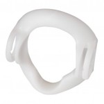
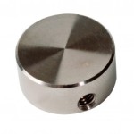
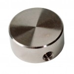
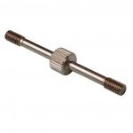
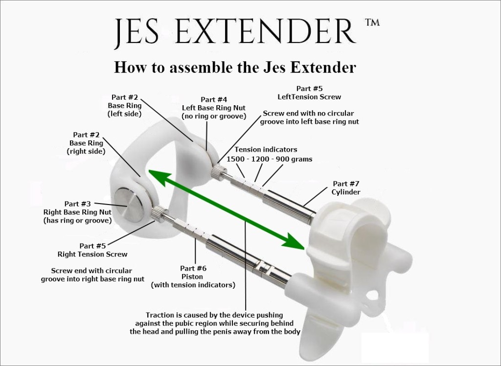
Firstly, please get familiar with the Jes Extender parts involved. We are mainly dealing with parts numbers 2, 3, 4, 5 and 6 as below.
- #2 Base Ring – $49.95
- #3 Base Ring Nut – Right $14.95
- #4 Base Ring Nut – Left $14.95
- #5 Tension Screw L/R $9.95
- #6 Piston – L/R $14.95
Jes Extender Assembly Instructions:
All parts can also be referred to here: Jes Extender replacement spare parts and accessories (opens in a new window/tab)
Putting back together the right side arm:
Step 1.
Holding on to the base ring as though about to put your penis through it – from the back to the front, we will use this position to determine our left and right sides for the base ring nuts (parts 3 & 4). Refer to picture below. If you are looking at the base ring from the front view, these will be reversed.
Step 2.
Place the right base ring nut (part #3) into the right side of the base ring (part #2). Important: the right base ring nut has a groove or ring indentation around it – the left does not. You must get this correct or the rest of the assembly will not be possible.
Step 3.
Get a tension screw (part #5) and locate the end with the groove or ring indentation. Important: only one end will have it, this is the only end used to screw into the RIGHT base ring nut (part #3). It will screw in to the left – or in an anti-clockwise rotation. Screw all the way down into the base ring nut (part #3) – but do not tighten.
Step 4.
Now get part #6 (the piston with tension indications) and screw it onto tension screw part #5. This part is usually connected with part number #7 which is the cylinder . Important: the correct piston will screw to the right, or in a clockwise direction. Screw all the way down onto part #5 – but do not tighten.
Note: Part #6 is directional meaning only the right handed side can be used for the right side. For example, only one of the pistons (part #6) you have will be able to screw in clockwise direction as directed above.
Putting back together the left side arm:
Step 1.
Place the left base ring nut (part #4) into the left side of the base ring (#2). Important: the left base ring nut has no groove or ring indentation around it – the right base ring nut does. You must get this correct or the rest of the assembly will not be possible.
Step 2.
Get a tension screw (#5) and locate the end with no groove or ring indentation. Important: this is the only end used to screw into the LEFT base ring nut (#4). It will screw in to the right – or in a clockwise rotation. Screw all the way down into the base ring nut (part #4) – but do not tighten.
Step 3.
Now get part #6 (the piston with tension indications) and screw it onto tension screw part #5. This part is usually connected with part number #7 which is the cylinder . Important: screw to the left, or in an anti-clockwise direction. Screw all the way down onto part #5 – but do not tighten.
Note: Part #6 is directional meaning only the left handed side can be used for the left side. For example, only one of the pistons (#6) will be able to screw in an anti-clockwise direction as directed above.

